2014
---
2
Governing Equations
The constitution equation.
Boundary Conditions
•
CaseA- the lung was fixed at the
trachea (1).
•
Case B - the rib cage and diaphragm’s
tendonwere fixed (2).
•
Hydrostatic pressure of the liquid was
defined in the lower lobe (3).
3.2. Flow simulations
:
Numerical technique
•
Geometrical model assembly:
SolidWorks3DCAD.
•
Simulation package:ANSYS Fluent 14.5.
•
The numerical simulation method:
Finite elements. Steady-state.
•
The elements were defined as 3D, 18000
–200000elements tetrahedral with 4
nodes each.
Model Geometry
The lobe model consists of 1 liter volume
ellipse attached to inlet and outlet tubes.
Governing Equations:
•
Continuity equation.
•
Navier - Stokesequation with porous
medium.
Boundary Conditions
Velocity at the inlet tubewas 0.014 [m/s].
Students names:
Inbal Eshcoli
BarbaraFursa
Department:Medical Engineering
Advisor names:
Dr.Anat Ratnovsky,
Dr. SaraNaftali
PulmonaryDialysis - PartA/B
Length [m]
Stress [Pa]
The right lower lobegeometrical model
(dimension inmm)
Outlet
tube
Inlet
tube
Porous Medium
Displacement [m]
Stress [Pa]
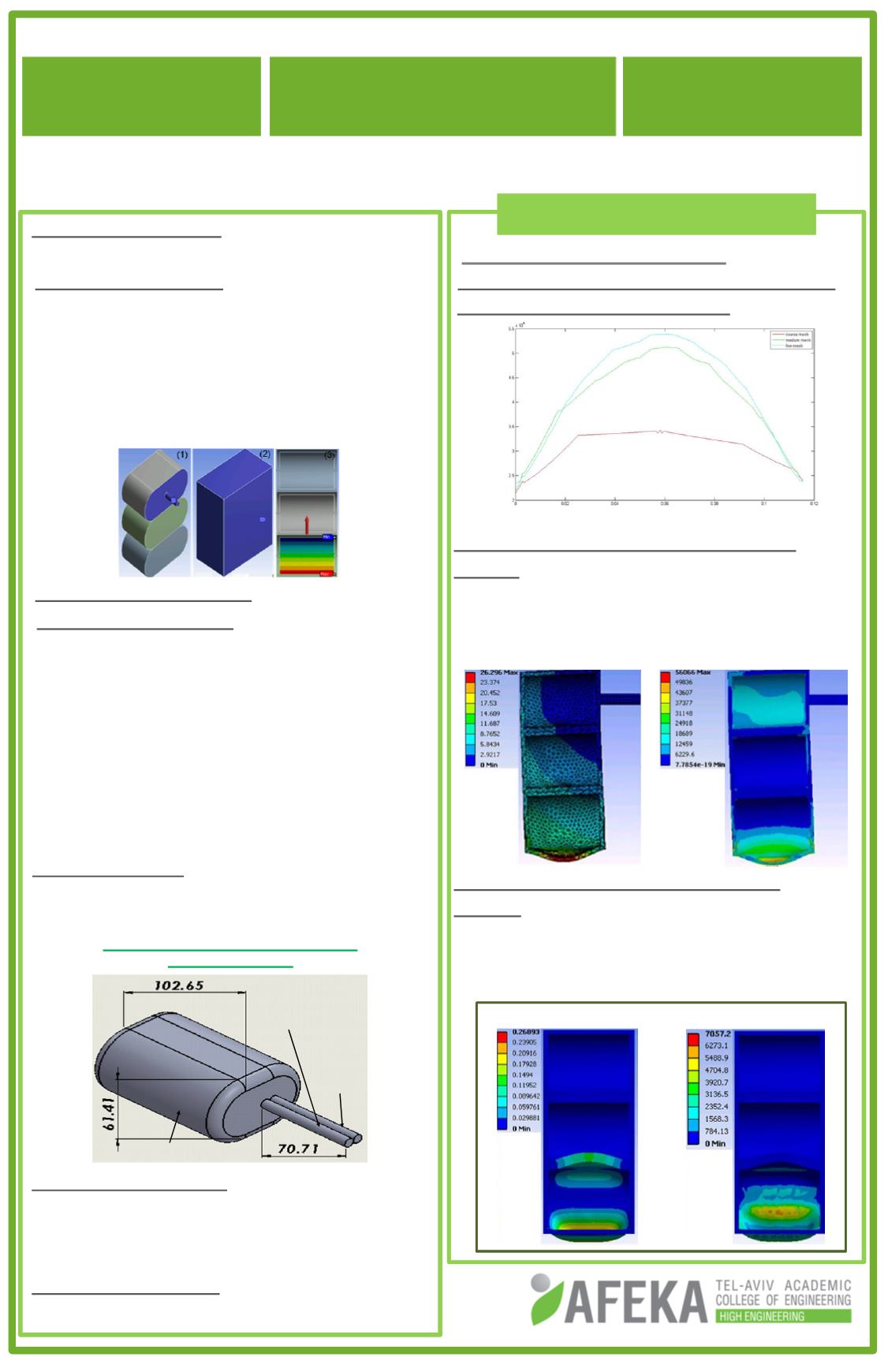
4.1Mechanical Simulations
Stress distribution along the bottom of the
lower lobe in 3different mesh:
Stress and displacement distributions:
CaseA
The liquid in the lower lobe causes large
stresses and displacement of the lower
lobe.
Stress and displacement distribution
CaseB
The stresses and displacements decreased
significantly in the constrained lung both in
the sitting (a) and supine (b) positions.
Stress [Pa]
Displacement [m]
(a)
4. Numerical Results


